
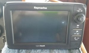
WARNING: this isn’t the normal “cool places we’ve been and people we’ve met” post. It’s one of my boring, how-to posts. Its intended audience isn’t the typical Smartini.Life reader, but rather, any boater who needs some help with her or his Raymarine e7D. If you don’t own one, you really don’t need to read this post. (But if you’re just dying to know, the e7D is our map – like Google Maps, and can also display the radar, the sonar, trip data, our backup camera, our FLIR infrared night vision camera, and any combination of two of those things. That’s why it’s called an MFD – Multi-Function Display.)
 We have four e7D’s on Smartini – two at the lower helm station, two at the upper. We bought them because, at the time, they were phasing them out and we could get them for a LOT less money than the newer, bigger replacement model. We don’t love them, but we don’t hate them, either. We always use a tablet with Navionics software and charts for route planning, and as a backup. They work. Well… three of them do. The night before we were to depart Florida for the Bahamas and beyond – literally hours before! – the screen on one of them started showing only varying shades of green and white. Fortunately, it was the one at the lower helm station (we almost never run the boat from there), and the one that was not designated as the “system master”. So no great loss.
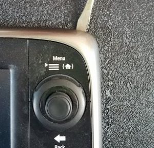
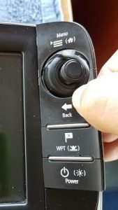
Several weeks ago, we noticed that the big knob that’s used primarily for zooming in and out on the chart started behaving erratically. It wouldn’t zoom smoothly, and sometimes while zooming in, it would suddenly zoom out several levels. And when we turned the knob, it felt “sticky”.
I searched online and found other people reporting the same problem, but the solution was always “send it in to Raymarine for service”. But we’re in Turks and Caicos, so getting a unit to and from them would be a real hassle. And the units are all out of warranty. And the cost to repair one would likely be way more than I would want to pay – especially when considering shipping. So I says to myself – “Self, there’s no harm in taking the one with the bad screen apart, and seeing if you can get all the way to the knob. If you can, then take its knob and put it into the one with the bad knob.”
Two hours later, the job was done! (One of those rare boat repairs that actually goes exactly like you hope it will.) Below are the steps to disassemble the unit all the way to the point that the only thing left is the screen in the frame. (I didn’t see any point in taking that apart, as I didn’t have a spare screen to put in anyway.)
Tools you will need: thin bladed flat screwdriver, regular and small Phillips screwdriver, 3/32 (and maybe 2.5mm) hex head wrench.
Gently! You’ll notice I use that word a lot in the instructions. I mean it – some of these parts are rather delicate, and if you break one, you’re probably screwed. So take it easy, Hercules!
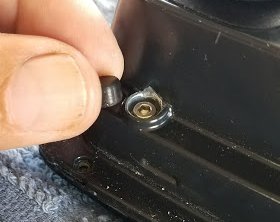
 1. Remove plastic trim bezel by gently prying it up with a very thin-bladed flat screwdriver.
2. Remove 4 screws in the corners that mount it to the panel. Pull the unit from the panel and disconnect the cables from the backside, and place it face down on a towel or other soft, cushioned surface.
 3. Gently lift off the whole button / knob cover piece. You should be able to do this with only your fingertips.
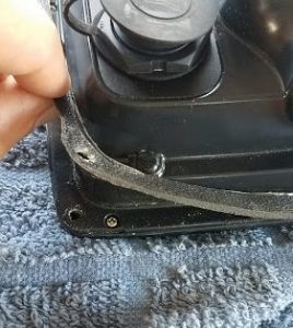 4. Gently remove the thin gasket that goes all around the unit where it mates to the panel. That exposes 14 small Phillips head screws.
5. Remove the 14 screws.
 6. Using your thumbnail or a small screwdriver, gently pry up the four screw covers (one at each corner).
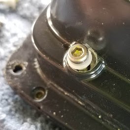 7. With an Allen wrench, remove the four screws that you just uncovered. They are TIGHT – be sure to use the correct size wrench. I was able to remove all but one with a 3/32”, but for one, I had to use a 2.5mm. Just be very careful to not strip the head. A plastic bushing will come out with each screw – don’t lose those! They are what align the two halves perfectly when you reassemble them, so that the many-pin electronics connector lines up.
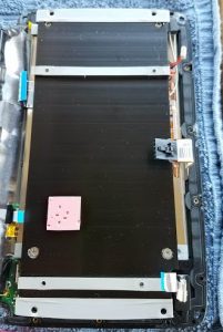
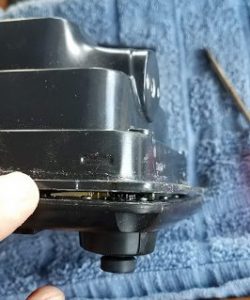 8. Use a thin flat screwdriver to separate the two halves of the unit, starting at the corner. Work your way around until the halves are separated, then gently pull them apart. They connect to each other through a many-pin connector that will automatically properly align and reconnect when you put the two halves back together later.
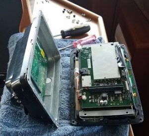
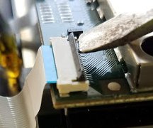
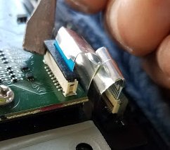
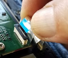
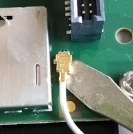 9. Disconnect the little gray wifi antenna wire connector and all the other connectors around the unit. There are four ribbon cable connectors that are held in place by a thin black latch: lift the latch, and the ribbon cable will slide right out. (See the next three pictures.)
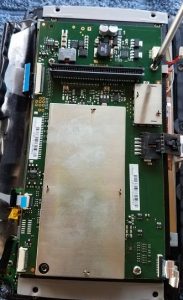
10. Remove the four Phillips head screws that hold the main circuit board in place.
11. Lift up the circuit board that those four screws held in place. It will be a little sticky, because of a pad of pink insulation between it and the heat sink that it’s screwed to.
12. Remove the four Phillips head screws (two flat head, two rounded head) in the heat sink, and lift off the heat sink. On my two units,the flat head screws were quite tight, so make sure to use the correct size screwdriver for a good fit, and – you guessed it – be gentle, but firm.
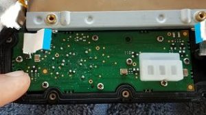 13. Remove the nine tiny screws that hold the button / knob circuit board in place. Don’t lose the white silicone spacer – it’s not fastened on – and don’t forget to put it back in place before reassembly.
 14. Gently lift up the circuit board, separating it from the silicone gasket.
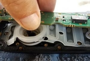
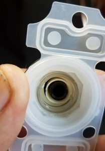 Inside the external knob, which is now visible, you may see what I saw – that the white plastic part that should turn when the knob turns is broken. I’ve emailed Raymarine to see if I can buy just that part, but I just know they’re going to say no. (UPDATE: I contacted them, and they said “yes”! I ordered part number R70227, which is just the knob assembly. It was $54 – but if another one breaks, I’ll be ready for it!)
At this point, the only thing remaining to remove would be the screen from the front half of the case, and I didn’t see any reason to do that, at least not in my situation. Even if I were replacing the screen, I think I’d replace the screen and front half as an assembly, rather than try to remove the screen. (It seems to be in there pretty securely, and I couldn’t see any way to remove it.)
Reassembly is the simple reverse of the above disassembly steps. The only two slightly tricky parts I encountered where when reinstalling the thin gray antenna wire (it snaps straight down onto the connector), and the button / knob cover on the front (insert the left side as fully as you can first, then snap the right side into place).
I hope this was helpful to you. If you’d like to see my other How To posts, they’re all in the Maintenance category.
Hi, just came across your article on dismantling the Raymarine E7 MFD. I have one of these and recently have lost the GPS signal, have you experienced this with any of your MFD’s, if so was there a solution. Also someone on another forum has suggested there may be a ‘penny battery’ inside the unit that might need replacing, did you come across one of there when you stripped it down.
Thanks
Barry McCrae
Barry, I’ve had some issues with the internal GPS on the MFD’s, which I solved by making sure that all of them on the boat do NOT use the internal GPS antenna. (Which then makes them look on the network for a GPS signal, which they find because I have an external GPS antenna connected to the network.)
I didn’t come across a battery, but I also didn’t take the unit completely apart, so there might be one. Google, or the user manual, should help you with an answer. But wouldn’t be surprised if there is NOT one, as I think it would be used only to maintain the time, and I think the time is typically setup to come from the “network time”, which comes from the GPS signal.
Hi Brian, thanks for the prompt reply. Looks like the easiest option will be connecting an external GPS.
Hi Brian, just thought you might be interested in an update on the E7. Stripped the unit down following your instructions above (which are excellent) but could not find any sign of a small battery. Also tried looking for what might be the GPS, looked at several components under a magnifying glass but couldn’t find the GPS. Remembered that I had a contact at Raymarine Service UK, sent him an email with the details, he promptly replied pointing me in the right direction to find the GPS, located the PCB with the GPS on it, took a photo, sent this to Raymarine who confirmed it was the correct PCB, he said the GPS looked faulty (wasn’t sure how he was able to deduce that from the photo), I asked if they had the PCB in stock which they did. A replacement was sent to me just before Xmas, arrived last Thursday and installed into the chartplotter later that day. On testing the GPS worked perfectly – a result – however unfortunately my charts were now not showing up. Have had a further play around with the unit over the weekend, stripped it down, checked connections and now it is all working perfectly again.