

(To the regular readers of Smartini Life – skip this one! I’m starting to build a library of straight-up “how to” articles for other boaters, and this is the first one. I can’t imagine you’ll find it interesting!)
This is a step-by-step article on how to remove and replace the hydraulic cylinders on a Wesmar stabilizer system (one on each side). In my case, I did this because the seal on one cylinder started to leak. Hopefully, in your case, you’re doing it as preventive maintenance.
I needed some technical support a couple times during my project, which I got by calling Wesmar directly, and speaking to a wonderful man named Jason Smith. He seems to know these systems intimately, because he had the answers I needed in his head – he didn’t even have to pause to look them up. 425-481-2296.
I couldn’t find any definitive information on how often to service the cylinders and the fin shaft seals, so here’s what I’m going to do. You need to do your own research, and do your service when it make sense for you. My schedule may seem aggressive, but since we plan on being in a lot of places that are a long way from being able to haul out, I’d rather be safe than sorry.
– Replace fin shaft seals every three years (for me, that’ll be at alternating haul-outs).
– Rebuild the cylinders at the same time.
– Replace the hydraulic lines every ten years.
My system was installed when the boat was built in 2002. The various Wesmar manuals that came with the boat when we bought it are dated 1995, 1999, and 2005, and they’re all consistent. The only differences I see mentioned are the size of the fins – presumably bigger boats used bigger fins. But all the rest of the documentation I have found seems to indicate that everything else about the system – at least about this part of the system – was the same for many years.
If you have all the tools you need, and easy access to everything, you should be able to remove each side in 30 minutes or less by following these instructions. Reassembly may take a little longer, depending on how good your grease gun is. (Seriously – getting grease where I wanted it was the hardest part of my reassembly!)
Things You Will Need
Aside from normal hand tools, you’ll want some things you may not have in your toolbox.
– First and foremost, you’ll need plugs for the four hydraulic hoses you’re going to disconnect (two on each side). If you don’t plug them, you have a very good chance of losing a lot of fluid out of them during the time it takes you to get your cylinders rebuilt and ready to reinstall. Masking tape won’t cut it! The fact that the bi-directional valves are supposed to center in the closed position doesn’t seem to matter. GET PLUGS! (Don’t ask me how I know.)
– LOTS of rags and diapers or other oil-soaking cloth. This is the messiest job I have performed on the boat to date, and I sure hope I never have a messier one. Hydraulic fluid will leak, and get on your hands, and your tools, and all the parts of the system. When you’re greasing all the fittings during reassembly, grease will spooge out of various places, and get on your hands, tools, and everything. So have more rags than you think you’ll need, and use them often. (Don’t ask me how I know.)
– 90 degree Phillips head screwdriver, for one or both of the screws that hold the potentiometer cover in place.
– A hex head bolt socket, for the six large bolts that hold the upper housing in place. On mine, the size is 5/16″.
– A grease gun with waterproof (or water-resistant) grease. The Wesmar manual calls for Lubriplate Marine A, but I couldn’t find that, so I went with Lubriplate Marine Grease. It’s thinner than the grease that was in there, but I don’t know if the grease that was in there was what it should have been.
– If all four of yours aren’t in great shape, you may need to replace one or more of the “E” clips that hold the large clevis pin in place (one on the top and bottom of each pin, one pin on each side of the boat). (See Step 15.) Neither Home Depot nor NAPA had ones that were big enough – I found mine at Fastenal.
Disassembly
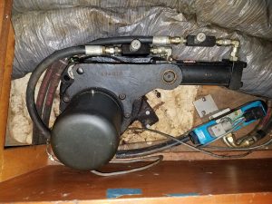
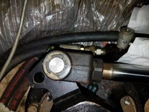
1. Locate the stabilizer actuators. There’s one on each side of the boat (one for each fin). On our boat, one is under the bed in the Master Cabin, the other is under the floor of the hanging locker in the Master Cabin. Yours could be anywhere. Here’s what the whole thing looks like:
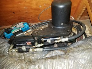
It consists of a large “arm” that’s connected to the shaft on which the fin is mounted, so moving the arm rotates the fin. The arm is moved by a hydraulic cylinder (that’s what we’re going to remove), which is held in place (and rotates on) two heavy “pins”, which go into holes in the lower housing (mounted to the hull) and upper housing (which you’ll remove). The cylinder is controlled by a bi-directional hydraulic valve (the blue thing). The valve is controlled by the “brain box” (mine is mounted in the engine room), which gets input from an electronic gyro (mine is located under the lower helm) for detecting the boat’s roll, and from a potentiometer at the end of each fin shaft, which gives an electrical signal to the brain box about the current position of the fin. Basically, when the boat rolls, the gyro sends that info (speed and degree of roll) to the brain box. The brain box then determines how much correction to give (how much to move the fins), and uses the bi-directional valves to send hydraulic fluid in the right direction for the right amount of time, which it determines in part by monitoring the fin position via the potentiometer. Clear as mud?
2. First, prepare you work area by removing anything that might be in the way of you being able to swing wrenches, and by putting a cloth of some sort under the entire assembly, to catch the fasteners that you will inevitably drop at some point. I put a towel under the unit, as I have a real “black hole” into which anything dropped would be gone forever. (Don’t ask me how I know.)
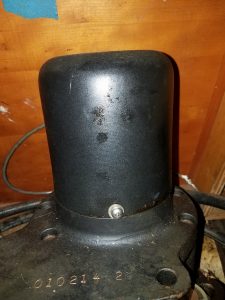
3. Remove the “pot” (potentiometer) cover by loosening the two Phillips head screws at the base of the cover. You don’t have to remove them – just loosen them. In my case, I had to use a 90-degree angled head screwdriver to access one of them. When you have the screws loose, gently lift the cover, feeding wire into the inside of the cover as you lift it so you don’t pull on the wires inside. Feed enough wire into the cover so that you can set it aside, well out of your way.
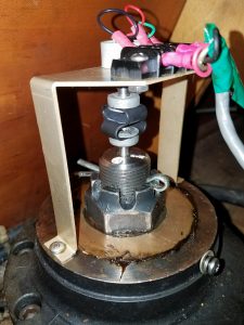
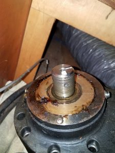
This is what you’ll find under the cover. In this Image 4, you can barely see the pot on top of the mounting bracket (with the wires going to it), and underneath, you see the flexible coupling between the bottom of the pot and the top of the fin shaft. As the fin is moved by the hydraulics, the shaft rotates, which rotates the flexible coupling, which turns the knob on the bottom of the pot, which changes the electrical output from the pot, which is sent to the brain box. This is how the system always knows the position of each fin.
4. With a permanent marker, put a mark on top of the big fin shaft, and on the side of the flexible coupling, so that when you reassemble, you can line those marks up. You don’t have to be exact, as you’ll do a final adjustment at the end of the reassembly process, but make it close. Also, mark the orientation of the bracket that holds the pot, before you remove it. It will fit both ways, but if you get it back on wrong (180 degrees off), the final adjustment will be harder. (Don’t ask me how I know.)
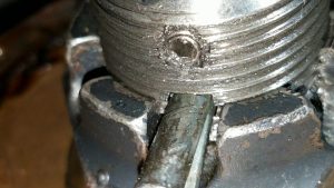
5. To remove the pot, mounting bracket, and flexible coupling, you have to first loosen a hex head screw that screws into the side of the shaft, above the castle nut. (Image 5.) On one of my units, it was easy to find. On the other, I had to use a mirror to locate it, as it was between the shaft and the base of my hanging locker, with only a few inches in between. Use an Allen wrench to loosen it (DO NOT REMOVE IT!), so that you can freely spin the flexible coupling.
6. Remove the screw at each base of the pot mounting bracket and lift the bracket (with the pot and flexible coupling attached) straight up until it’s free from the shaft. Set it aside, well out of your way – you don’t want to smash a wrench into it later! And be careful with the wires – they’re small and delicate.
7. Now you have wide open access to the castle nut and cotter pin on top of the shaft. Remove the cotter pin and the nut. Don’t worry, the shaft won’t fall out of the hull – probably. 🙂 It’s secured by a clamping mechanism lower on the shaft, and also, the fin SHOULD be buoyant, so that it will try to float up into the hole, not fall down out of the hole. (But if your fin is damaged, it could be full of water, and could try to fall out.)
DISCLAIMER: I’ve done this job only once, and one of my shafts did drop down about half an inch before the lower clamping mechanism kept it from going any farther – which freaked me out! But not a drop of water came in, and I secured the shaft back into place once I got the cylinder removed (Step 18), and I suggest you do the same. Also, pay very close attention at this point, in case your shaft seals aren’t in great shape, as you could get some water coming in after the castle nut is removed.
8. In Image 6, you can see a large bronze thrust washer around the shaft. You shouldn’t need to remove that at this point – it will come off when you lift the upper housing. (Then you can easily remove it to expose the roller bearings underneath, which you’ll want to clean and regrease prior to reassembly.)
9. Remove the six large hex head bolts around the upper housing. (You can see three of them in Image 6.)
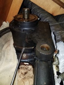
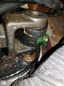
10. At this point, the upper housing is no longer fastened to anything, but it’s likely to be pretty snug. Use a large flat blade screwdriver (or two – one on each side) to pry it loose. Once you’ve pried it up even a little bit, you should be able to lift it straight up and off of the shaft. See Image 7 to know where to insert the screwdriver for prying.
11. Remove the upper housing and set it aside. This exposes the clevis and clevis pin that attaches the moving part of the cylinder (the ram) to the lever arm. You should also now have good access to the small hydraulic hoses that connect to the cylinder.
11a. Lift the bronze thrust washer out of the upper housing, and inspect the roller bearings underneath. If the grease is clean and the bearings look to be in good shape, they should be fine to go back together. If the bearings are pitted, you’ll need to replace them. Mine were fine, but I’m guessing if you had to replace them, you’d have to contact Wesmar to get the right ones.
12. Put a diaper or other oil-absorbent cloth under the fittings on the cylinder to catch the hydraulic oil that will ooze out. I use actual baby diapers for this kind of job, with the stretchy sides ripped off unless I want a “bucket” shape, then I leave them on.
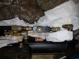
13. Using tape and/or a Sharpie, mark each hose so you know which one goes on which fitting. You think you’ll remember… but don’t take the chance – mark them!
14. Loosen the fittings and remove them, catching all of the oil in the diaper. NOTE: once the hoses are removed, the oil still in the cylinder will squirt out with some authority if you move the ram in or out – so don’t do that, until you’re ready to catch that oil. (Don’t ask me how I know.) Better yet, if you have caps, put them on as soon as you disconnect the hoses.
The bi-directional valve that controls the flow of fluid to these hoses is closed at rest, so no fluid should come out of the system other than that which is in the small hoses to the cylinder, and the cylinder itself. But plug those hoses, as fluid can leak out! If you don’t plug them properly, and you accidentally start the stabilizer system, you’re going to have hydraulic fluid EVERYWHERE! (No, I didn’t do that. In fact, I disconnected the wire at the stabilizer manifold, specifically to prevent this from happening.)
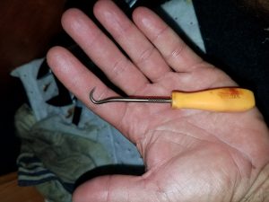
15. Remove the “E” clip on top of the clevis pin. I used a little scraping tool that had a hook on the end to simply pull the clip away from the pin. Be careful – the clip may want to go flying!
16. Push the clevis pin down into the hole, giving you better access to the “E” clip on the bottom of the clevis pin, and remove that clip, too, Then you can pull the pin up out of the hole.
17. Now, simply lift the cylinder straight up. Be ready to catch the hydraulic oil that will inevitably ooze out of the fittings. I suggest you put the whole thing in a bucket.
18. Unless you have a replacement cylinder ready to install right now, I suggest you now replace the upper housing (which you removed in Step 11), and loosely reinstall the six long hex head bolts, the bronze thrust washer, and the castle nut. This will keep the shaft from being able to drop at all, giving you the peace of mind you need, knowing that you’re not going to sink the boat while the cylinder is being rebuilt. Also, put the locking pin (you do have your locking pins, right?) in place to keep the fin from rotating. (Basically, do a loose reassembly of the system, without the cylinder, until you’re ready to reassemble it with the new or rebuilt cylinder.)
Rebuild or Replace the Cylinders?
After getting input from several sources, I decided to have mine rebuilt. They were in excellent condition (the ram must be, or it will always leak), and I found a marine hydraulics company (Ramsay Marine, in Riviera Beach, FL) that does fantastic work. They pressure tested them before they took them apart, and found not just one, but both of them, to be leaking (one much worse than the other). They rebuilt them (which they said doesn’t require any special tools or even seals that aren’t commonly used by hydraulics repair shops), pressure tested them to 1000 psi, and shipped them to me in about a week. The total cost was significantly less than the cost of two brand new cylinders.
But if yours aren’t in great shape – if the ram is pitted – replacement may be your only option.
Reassembly
It’s pretty much the reverse of the disassembly process, with a few twists.
1. Reverse Step 18 above, to remove the upper housing.
2. Grease the fitting on the lower housing, now, before you cover it up with the cylinder. On mine, I never had grease come out anywhere I could see, so I just greased it until the pressure started to increase on the handle of the grease gun. My guess is the oozing out was taking place on the bottom of the housing (around the fin, under the hull), so I eventually stopped.
3. Put the cylinder in place. Be sure to orient it correctly, with the arm pointing in the general direction of the fin shaft, and the fittings on the same side as the hoses you have to reconnect. Once it’s in place, grease the fitting until grease oozes out of somewhere, or the pressure on the handle of the grease gun gets really hard (because it can’t put any more grease in).
4. Put an “E” clip on one end of the clevis pin and have it ready to put in place. Rotate the lever arm (the arm that’s clamped to the shaft, that has a hole in the end) so that it lines up with the holes in the clevis on the end of the cylinder ram, and insert the clevis pin through all three holes. Put the “E” clip on the bottom of the clevis pin. This may be difficult – you may want a helper for this step! If you’re in completely calm water, moving the arm / shaft / fin is tough. If the water under the boat is moving, it’s very difficult, even with a helper.
At this point, you can see how the whole hydraulic system works: the blue bi-directional valve sends fluid into one end of the cylinder or the other, which moves the ram, which moves the lever arm, which rotates the fin shaft, which moves the fin.
5. Attach the hydraulic hoses and tighten the fittings. Tight, but not too tight. Depending on the angle of the hoses and fittings, you may have to do them in a certain order. On mine, I had to do the short one first, because if I had done the long one first, it would have been in the way of doing the short one. Pay attention.
6. If you didn’t do this during disassembly, remove the bronze thrust washer from the upper housing and inspect the grease and the roller bearings. Hopefully the bearings are in good shape, because if they aren’t, you’re going to have to pause the project at this point until you can get replacements.
7. With the thrust washer removed, gently lower the upper housing onto the shaft, so that the hole in the “arm” part of the housing fits over the “pin” on the cylinder. (Not the clevis pin, but the short round “shaft” that’s part of the cylinder housing.) Now, the cylinder is held in place by the lower housing and the upper housing, so all it can do is rotate a little, as the ram moves in and out.
8. Put the thrust washer in place. If there is a hole in it, position that hole on the opposite side of the shaft from the grease fitting in the upper housing, and keep the hole in that position when you later tighten the castle nut.
9. Start, but don’t tighten, all six of the large hex head bolts that hold the upper housing in place.
10. Put the castle nut on and tighten it. Not as tight as you can get it – just a little less than that, so that the cotter pin will go through the hole in the shaft. Put the cotter pin in and bend one or both of the ends.
11. Grease the fitting on the upper housing that puts grease all around the shaft and under the thrust washer. In my case, I greased it until grease oozed out of the hole in the thrust washer. (That’s why I positioned the hole opposite the grease fitting – so that grease wouldn’t come out of the hole until it had filled the area underneath.)
12. Tighten all six hex head bolts to secure the upper housing.
13. Replace the pot bracket, making sure it’s oriented properly. (It will go on either way – and it’s not the end of the world if you get it wrong. But if you put it back on the way it came off, it makes the final adjustment a little easier. Don’t ask me how I know.)
14. Line up the marks on the flexible coupling and the top of the fin shaft (the marks you made in Step 4 of the disassembly process), and “snug” the hex head set screw that keeps the flexible coupling from turning. (See Step 5 of the disassembly process.) You want it tight enough that the flexible coupling can’t spin freely, but loose enough that you can twist it with your fingers.
If you didn’t make marks – no worries – the final adjustment will just take a little longer.
15. Now you’re ready to test. Move all your tools out of the way. Move the pot cover and the wire out of the way of the cylinder and lever arm. (These are the only moving parts.) Make sure you tightened the fittings on the cylinder – tight, but not TOO tight. Start the engine to get hydraulic fluid pumping. Turn on the stabilizer system and leave it in “Standby” mode. Inspect your hydraulic lines at the cylinders for leaks.
You shouldn’t need to bleed air out of the system – it should be self-bleeding. New fluid is constantly pumped into each side of the cylinder as it’s moved, and the old fluid (in the other side) is returned to the tank.
16. On each side, one at a time
– If the locking pin can slide into place, through both holes, the fin is centered properly, and you can tighten the hex head set screw. But it’s probably not, because it’s unlikely you got the flexible coupling perfectly aligned when you re-installed it. So…
– Twist the flexible coupling a tiny bit, in either direction, and see what happens to the alignment of the locking pin holes. Keep twisting the coupling, a little at a time, one way or the other, until the holes stay lined up. When they are lined up, that’s centered. Now you can tighten the hex head set screw, nice and tight.
– IF YOU DIDN’T MAKE MARKS, or if you installed the pot bracket 180 degrees off (like I did), it may seem like no matter what you do, you can’t get the fin to center, indicating that you’re WAY off. So twist it all the way one direction, or all the way the other (still just a little at a time, though). Eventually, you’ll get it in the ballpark, and then you can fine tune, until the holes line up. (If you suspect you put the bracket on “backwards”, you could remove and replace it the other way, but it’s probably just as easy to do what I did – just keep twisting until it all lines up.)
17. Replace the pot cover, gently feeding most but not all of the wire out of the cover as you put it in place.
18. Get clean rags and clean up all of your tools. Wipe up all the hydraulic fluid that leaked out, and all the grease that spooged out, and make everything nice and clean, especially around the hydraulic fittings. (That’s how you’ll know later that you have a leak – if an area you made completely clean and dry is no longer clean and dry, you probably have a leak.)
Post Op Instructions
It’s probably a good idea to visually inspect the whole actuator mechanism very shortly after you use the stabilizers the next time. I don’t mean after an 8 hour run with stabilizers on – no, I mean after using them for maybe 5 minutes (in conditions that require the stabilizers to activate). If you have a hydraulic leak that happens only under serious load, you want to find that out before you dump a gallon or five of hydraulic fluid into the bilge. (No, I didn’t do that!)
Great post. You mention that you don’t have to bleed the system. My manual, which is a scattering of random pages at best, indicates when the filter is change that the system has to be bleed by jogging the system, which I have no idea how to do, until all the air bleeds through the plug then tighten the plug. Any suggestions would be appreciated.
Richard,
I didn’t change a filter, and I didn’t have to bleed the system. Activation of the stabilizers seems to do the job.
Such a thorough explanation. Thank you. How many hours did it take from start to finish and how do you think that would compare to an authorized Wesmar mechanic?
I did that so long ago, I can’t really remember how long it took. Probably an hour to 90 minutes per side to remove, then an hour per side to put back together. I’m sure a Wesmar tech could do it faster, but the end result would be identical.